







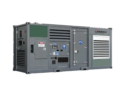
How to Design a Multi-Generator Paralleling System for Large Industrial Projects?
Release time: 2026-09-17
Table of Contents
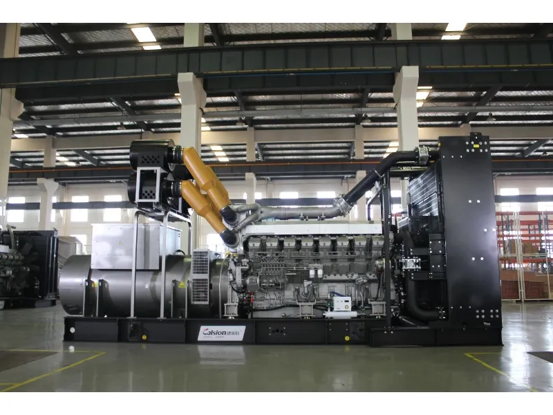
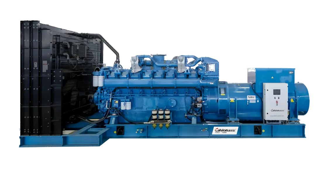
Large-scale industrial projects are typically characterized by high load demands, complex electrical equipment, and long operating hours; a single diesel generator often struggles to simultaneously meet requirements for peak power, continuous supply, and backup redundancy. A multi-generator paralleling system enables multiple units to operate in coordination, achieving load sharing, automatic synchronization, and flexible scheduling. This not only enhances power supply reliability but also provides greater flexibility for future capacity expansion. Therefore, designing such a system requires a comprehensive assessment of key factors, including project load, unit capacity, synchronization control, redundancy configuration, and the site environment.
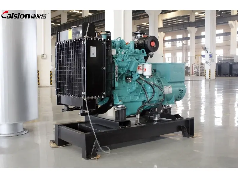
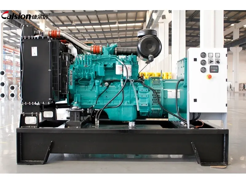
1. Why Should Large Industrial Projects Use Paralleled Generator Sets?
Large factories, mines, oil and gas facilities, data centers, and infrastructure projects typically have high power demands, and the load variations across different production equipment can be significant.
Relying on a single large diesel generator requires sizing the unit based on the project’s maximum load. However, in actual operation, the equipment may frequently run at partial load, resulting in inefficient utilization of the large generator.
Paralleling multiple units allows the number of active generators to be flexibly adjusted based on the actual load. For example:
Fewer units operate during low-load periods;
Additional units are automatically brought online as the load increases;
Multiple units operate simultaneously during peak load periods;
Other units maintain the power supply while one unit undergoes maintenance.
Paralleling multiple units also enhances redundancy for critical loads, making it a common choice for projects requiring high power supply continuity. Technical documentation for paralleling systems from manufacturers like Cat and Cummins highlights load sharing, redundancy, scalability, and system reliability as key design objectives.
2. How Many Generator Sets Does the Project Need?
Determining the number of generators is the first step in designing a paralleling system.
The engineering team must first compile a comprehensive load schedule, including:
- Normal operating load
- Maximum operating load
- Motor starting load
- Peak load
- Critical load
- Non-critical load
- Future expansion load
Generators cannot be selected simply by summing the rated power of all equipment.
For instance, large water pumps, compressors, fans, and production equipment can generate significant inrush current at the moment of startup. Insufficient generator capacity can lead to startup failures, frequency drops, or voltage fluctuations.
Therefore, it is necessary to analyze both steady-state and transient power requirements.
For high-reliability projects, redundancy designs such as “N+1” can be employed; this involves adding a backup unit to the “N” units required to meet actual project needs. If one unit fails or undergoes maintenance, the remaining equipment can still carry the critical load.
3. How Does Generator Synchronization Work?
Multiple generators cannot simply be connected and run simultaneously; they must undergo rigorous synchronization control.
Before a unit is connected to the common busbar, the following parameters must be matched:
Voltage + Frequency + Phase Sequence + Phase Angle
The generator circuit breaker can only close safely once the generator’s output parameters meet the specified conditions relative to the common busbar.
Modern paralleling systems typically handle this process using automatic synchronizing controllers. These controllers continuously monitor the status of the generator and busbar, adjusting engine speed and alternator excitation to bring the unit into synchronization.
In a properly designed paralleling system, generator sets must be synchronized with the common bus before connection. The synchronization process typically considers voltage, frequency, phase sequence, and phase angle, with the synchronizing controller coordinating the generator controls and circuit breaker.
Consequently, in large-scale industrial projects, coordination among the synchronizing controller, generator controller, and circuit breaker is fundamental to the stable operation of the entire paralleling system.
4. How Is Load Sharing Managed Between Multiple Generators?
Once multiple generators are paralleled, the rational distribution of load is equally important.
Improper load distribution can result in one unit operating under a high load for extended periods while another runs at a low load; this not only compromises fuel economy but may also accelerate equipment wear.
Therefore, paralleling systems typically manage the following simultaneously:
- kW (Active Power) Load Sharing
- kVAR (Reactive Power) Load Sharing
- Automatic Load Balancing
- Automatic Start/Stop
- Load Addition / Load Shedding
- Peak Load Management
For example, as the factory load increases, the control system can automatically start additional generators and redistribute the load among the units.
This allows each unit to operate within an optimal range while preventing any single unit from running under overload conditions for extended periods. 5. Should the System Use Centralized or Distributed Control?
The control architecture is a critical decision in the design of large-scale paralleling systems.
Traditional solutions might employ a centralized controller to manage all generators; however, such an architecture requires careful consideration of the impact a central controller failure would have on the entire system.
An alternative approach is to use a distributed control architecture, where each generator possesses independent capabilities for synchronization, paralleling, and load control, while coordinating via a communication network.
The advantage of a distributed architecture is that it mitigates the impact of a single point of failure on the overall power generation system. A distributed control architecture can reduce the impact of a single controller failure by allowing individual generator controls to retain key synchronization, paralleling, and load-control functions. The suitability of centralized or distributed control should be evaluated according to the project’s reliability requirements, system complexity, and overall design.
For large-scale industrial projects, the appropriate control architecture should be selected based on project scale, reliability requirements, budget, and control complexity.
6. How Should Redundancy and Protection Be Designed?
Large-scale industrial projects require consideration not only of how power is supplied under normal conditions but also of how critical loads can remain operational during a fault.
A well-designed paralleling system should be capable of safely isolating a malfunctioning unit while allowing the remaining healthy units to continue operating.
Protection functions typically include:
- Overcurrent Protection
- Short-Circuit Protection
- Overvoltage / Undervoltage Protection
- Overfrequency / Underfrequency Protection
- Reverse Power Protection
- Ground Fault Protection
- Emergency Shutdown
Additionally, the system can employ prioritized load control to distinguish between critical and non-critical loads.
When available generation capacity drops, power supply to core production equipment, fire protection systems, communication systems, or other critical equipment can be prioritized, while non-critical loads are temporarily shed.
7. How Should the Common Bus and Switchgear Be Designed?
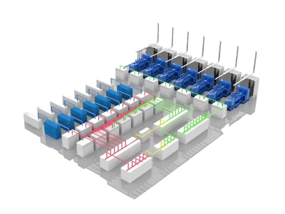
The core of a multi-unit paralleling system comprises not only the generators but also the paralleling bus, circuit breakers, switchgear, protection equipment, and the power distribution system.
A typical system configuration can be visualized as follows:
Diesel Generator Sets → Generator Breakers → Common Bus → Main Switchgear → Industrial Loads
Each generator must be connected to the common bus via an independent circuit breaker.
During the design process, the switchgear configuration must be determined based on factors such as the project’s voltage level, short-circuit capacity, number of generator units, and load requirements. For low- and medium-voltage projects, specific switchgear configurations and control methods can vary significantly; therefore, it is essential to complete single-line diagram designs and conduct analyses—such as short-circuit and protection coordination studies—during the initial project phase.
Multi-generator paralleling systems for large-scale industrial projects involve more than simply connecting multiple units; they require systematic planning regarding power requirements, load characteristics, synchronization control, load sharing, fault protection, and scalability. A robust solution balances operational efficiency and ease of maintenance while ensuring a stable power supply. Leveraging continuous technical innovation and extensive expertise, Calsion tailors diesel power generation solutions—spanning unit configuration, paralleling control, and system integration—to the specific power needs of diverse industrial projects, helping clients build power systems that are reliable, efficient, and scalable.