

Diesel Generator Paralleling: Working Principles, Synchronization Conditions, and Troubleshooting Guide
Release time: 2026-10-28
Learn how diesel generator paralleling works, the 4 critical synchronization requirements, and how to fix load-sharing imbalances and circulating currents.language guide for overseas buyers evaluating SDEC-powered generator sets
In heavy industrial operations, large-scale construction sites, marine shipyards, and commercial facilities, relying on a single diesel generator set creates significant operational vulnerabilities. When continuous power demand surges beyond single-engine capacities, diesel generator paralleling delivers a scalable, highly reliable, and fuel-efficient power solution.
By synchronizing multiple generator sets onto a common bus, operators gain dynamic load-following capability and fail-safe N+1 redundancy. However, operating generators in parallel requires a firm grasp of quasi-synchronization criteria and prompt troubleshooting of electrical imbalances.
This engineering guide examines the core mechanics of multi-generator paralleling, the four non-negotiable synchronization conditions, and proven remedies for high-frequency field faults.
What Is Diesel Generator Paralleling and How Does It Work?
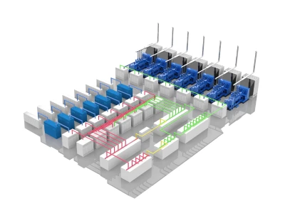
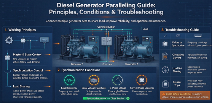
Diesel generator paralleling is the electrical interconnection of two or more generating units onto a synchronized common busbar to support a shared electrical load.
Rather than running one oversized generator at low, fuel-inefficient loads, a paralleled modular system automatically starts, synchronizes, and sheds engines based on real-time site power demand.
In automated power plants, an intelligent digital paralleling controller continuously monitors electrical parameters across both the incoming generator and the energized bus. By transmitting micro-adjustments to the electronic speed governor and the Automatic Voltage Regulator (AVR), the controller matches the incoming voltage, frequency, and phase angle before commanding the paralleling breaker to close safely.
4 Critical Conditions for Generator Synchronization
To close the circuit breaker smoothly—a process known as quasi-synchronization—without damaging physical drive components or destabilizing the grid, four precise conditions must be fulfilled:
1. Equal Voltage Amplitude (V1 = V2)
The output voltage magnitude of the incoming generator must align with the active busbar within ±5%. Any voltage delta induces reactive circulating currents across the stator windings, causing unnecessary heat dissipation and premature insulation breakdown.
2. Identical Operating Frequency (f1 = f2)
Engine speed directly controls AC frequency(). The frequency variance between the incoming unit and the bus should stay within ±0.2Hz (frequently calibrated to ±0.1Hz on precision digital controllers). Significant frequency differences cause violent kinetic surges during breaker closure.
3. Matched Phase Sequence (Phase Rotation)
The rotational order of the three-phase AC wave (U-V-W, A-B-C, or L1-L2-L3) must be completely identical. Attempting to parallel opposing phase rotations creates an immediate phase-to-phase short circuit across the switchgear.
4. Zero Phase Angle Displacement ( )
The sinusoidal peaks of the voltage waveforms must occur simultaneously, keeping the phase angle difference strictly under 10° at breaker closure. Closing out of phase generates catastrophic electromagnetic counter-torques capable of twisting engine crankshafts, snapping flex plates, and shearing rotor shafts.
Common Paralleling Faults and Troubleshooting Solutions
Even with modern digital controllers, dynamic on-site loads and field operating conditions can introduce operational anomalies. Below are three of the most common paralleling failures and their standard remediation procedures.
1. Unequal Load Sharing (Load Swings and Hunting)
The Problem: One generator set carries an excessive proportion of the load while another runs in an underloaded or reverse-power condition.
The Cause:
Active Power (kW) Imbalance: Caused by inconsistent speed droop settings, miscalibrated Electronic Control Units (ECUs), or poor fuel governor PID tuning.
Reactive Power (kVAR) Imbalance: Triggered by mismatched voltage droop percentages or faulty cross-current compensation transformers on the AVR.
Field Solution:
Re-calibrate speed governor droop percentages to ensure equal slope characteristics across all engines, or confirm load-sharing line continuity (analog lines or CAN-bus).
Check fuel filters and delivery systems to confirm mechanical output parity.
Adjust voltage droop trimmers on the AVR so reactive kVAR distributes proportionally to each generator’s kVA rating.
2. Synchronization Breaker Trip or Failure to Close
The Problem: The incoming engine reaches rated speed and voltage but hunts continuously without closing the tie breaker, or trips on synchronization protection.
The Cause: Excessive phase-angle drift, synchro-check relay window mismatch, or miswired phase sequence following site alterations.
Field Solution:
Verify phase rotation at both the incoming terminal and the bus side using an independent digital phase rotation meter.
Inspect the sync-check relay permissible window settings (dwell time, slip frequency, and allowable ). Highly fluctuating inductive loads often require slight tuning of these acceptance thresholds.
Check the motorized breaker mechanism, auxiliary contacts, and UVR (under-voltage release) wiring for mechanical lag or electrical dropouts.
3. Excessive Circulating Current (Cross-Current)
The Problem: Elevated line currents and high alternator temperatures occur even when overall site load demand remains low.
The Cause: Unequal open-circuit terminal voltages between parallel generators. The voltage differential drives current through a closed loop between alternators without delivering power to external loads.
Field Solution:
Individually measure the no-load terminal voltages of all units and adjust AVR setpoints to achieve identical output voltages.
Verify that cross-current compensation (droop CT) wiring, polarity, and burden resistors are installed correctly and consistently across all alternator frames.
Best Practices for Long-Term Paralleling System Reliability
Sustaining reliable multi-generator operations requires proactive preventative maintenance routines:
Sensor & Controller Calibration: Annually verify potential transformers (PTs), current transformers (CTs), and digital transducer inputs.
Communication Bus Integrity: Keep shielded twisted-pair cables for CAN-bus or Ethernet links isolated from high-voltage AC power conduits to eliminate electromagnetic interference.
Scheduled Load Bank Testing: Run periodic step-load tests to verify that dynamic transient response and speed/voltage recovery rates remain synchronized across the fleet.
FAQ
What happens if you parallel generators out of phase?
Paralleling out of phase produces a short-circuit-level electromagnetic shock torque. This transient surge can destroy the generator’s rotating components (breaking crankshafts and tearing drive couplings) and burn out stator windings instantaneously.
What is the difference between active (kW) and reactive (kVAR) load sharing?
Active load (kW) sharing is regulated by the engine’s fuel governor and rotational speed, dictating how real mechanical work is split across units. Reactive load (kVAR) sharing is governed by the alternator’s excitation system and Automatic Voltage Regulator (AVR), controlling how magnetic field energy and system voltage levels are balanced.
Why is digital paralleling preferred over manual synchronizing?
Digital paralleling systems use microprocessors to continuously adjust voltage and frequency in fractions of a second, closing the breaker at the exact millisecond of phase alignment. This eliminates human error, protects equipment, and enables fully autonomous load-dependent start and stop sequences.